CO2MPAS Model
CO2MPAS model is plotted here below: you can explore the diagram nests by clicking on them.
The execution of CO2MPAS model for a single vehicle is a procedure in three sequential stages:
Calibration stage: identifies, calibrates, and selects the best physical models (see next section Model selection) from WLTP input data (i.e.,
input.calibration.<cycle>).Model selection stage: selects the best calibrated models (i.e.,
data.prediction.models_<cycle>) to be used in the prediction stage.Prediction stage: forecasts the CO2 emissions using the user’s inputs (i.e.,
input.prediction.<cycle>) and the calibrated models. If some/all WLTP inputs are not provided, the functionselect_prediction_datachooses those required to predict CO2 emissions fromoutput.calibration.<cycle>.
The physical model is used in both
stages: calibration (i.e., calibrate_with_<cycle>) and prediction (i.e.,
predict_<cycle>). The identified/calibrated parameters from WLTP
data (i.e., data.prediction.models_<cycle>) can be grouped by functionality
in eight macro-models:
A/T: gear shifting strategy for automatic transmission,
electrics: vehicle electric components ( i.e., alternator, service battery, drive battery, and DC/DC converter),
clutch-torque-converter: speed model for clutch or torque converter,
co2_params: extended willans lines parameters,
after-treatment: warm up strategy of after treatment,
engine-coolant-temperature: warm up and cooling models of the engine,
engine-speed: correlation from velocity to engine speed,
control: start/stop strategy or ECMS.
Model selection
The default model selection criteria (i.e., when enable_selector == False)
are to use the calibrated models from WLTP-H data to predict WLTP-H and
NEDC-H and from WLTP_L data to predict WLTP-L and NEDC-L.
On the contrary, if the selector is enabled, the function
extract_calibrated_model
detects/selects the best macro-model for prediction (from WLTP-H or WLTP-L).
The selection is performed according to the model’s score, which is the model
capability to reproduce the input data, i.e. a weighted average of all computed
metrics.
In other words, the calibrated models are used to recalculate (predict) the inputs of the WLTP-H and WLTP-L cycles, while the scores are derived from various metrics comparing inputs against predictions.
Note
A success flag is defined according to upper or lower limits of scores which have been defined empirically by the JRC. If a score is outside the model fails the calibration and a warning is logged.
Hybrid electric vehicles model
Hybrid Electric Vehicles (HEVs) have more complex driveline layouts and control strategies compared to conventional vehicles. Their driveline integrates one or more electric machines for supporting propulsion and/or charging the drive battery, to regenerate braking power, using the engine at a more optimal operating point or even switching it off when appropriate. Therefore, additional components are needed for the simulation of their operation: electric machines, drive battery and DC/DC converter. The vehicle powertrain model of CO2MPAS is developed in a way to capture and replicate the operation of as many different vehicle architectures as possible through a unique driveline virtual architecture.
Hybrid electric architectures
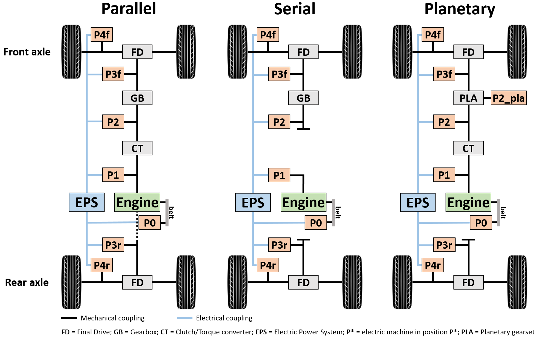
Three main architectures can be identified for HEVs driveline:
Parallel hybrids are similar to conventional vehicles as the engine produces mechanical power that is directly used for propulsion; also, engine rotational speed is a function of the rotational speed of the wheels according to the reduction/multiplication effect applied by final drive and gearbox (when present). The electrical machines are used to regenerate braking energy and optimise the load of the engine, but they cannot adjust the rotational speed of the engine when a gear is selected.
Serial hybrids have an additional degree of freedom for the optimisation, as both the load and the rotational speed of the engine can be selected by the controller. This is possible due to the lack of a mechanical coupling between the engine and the wheels. Therefore, a serial hybrid is always propelled by the electric machines and the engine is used to generate electrical energy that is used for propulsion or battery charging.
Planetary architecture is instead a driveline configuration that can accomplish, to some extent, the operation of the two architectures previously mentioned. The engine can provide mechanical power that is directly used for propulsion, but at the same time, its rotational speed can be adjusted by the controller becoming independent from wheel speed. This system normally replaces the conventional transmissions (gearboxes and CVTs) as it can adjust the reduction gear ratios to any wanted value, and it integrates two electric machines (one generating and the other one consuming electrical energy).
Electric power system
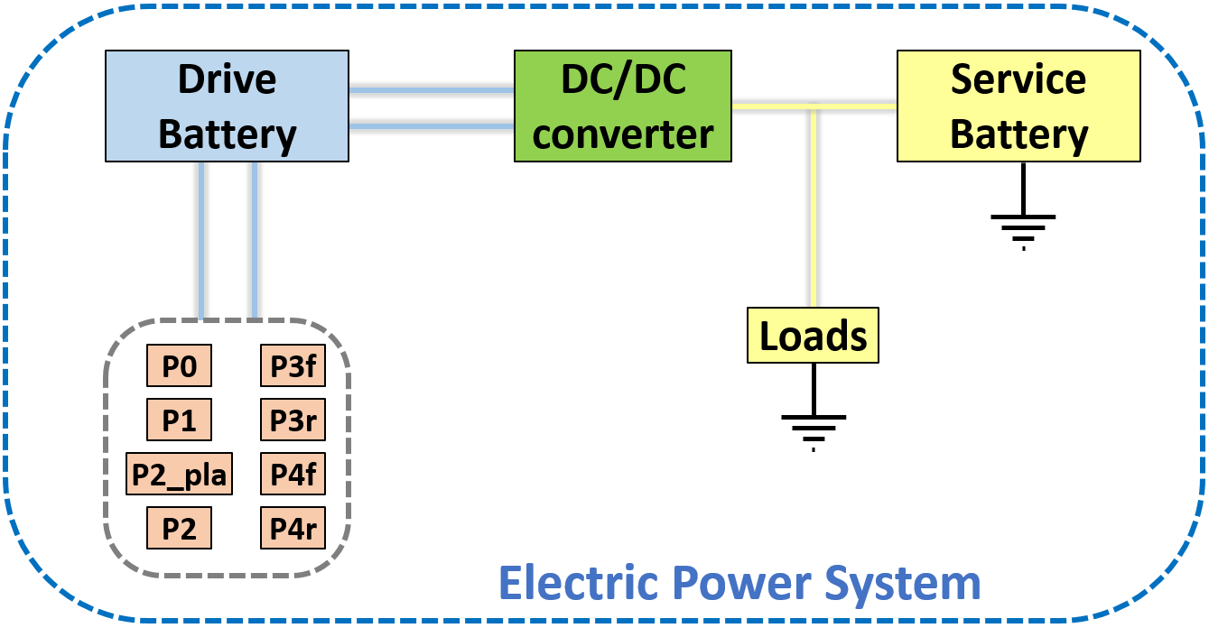
The Electric Power System (EPS) of HEVs is composed by three main components:
Electric machines (P0, P1, P2, P2_pla, P3f, P3r, P4f, and P4r),
Batteries (Drive and Service, i.e. high and low voltage batteries), and
DC/DC converter
The electric machines convert electrical energy into mechanical energy when they need to propel the vehicle and mechanical energy into electrical during regenerative braking or battery charging. This electrical energy, consumed or generated, is exchanged with the drive battery. The DC/DC converter is the component in charge of allowing the energy exchange between the drive battery and the low-voltage electric system of the vehicle, to supply the electrical consumers and charge the service battery when needed.
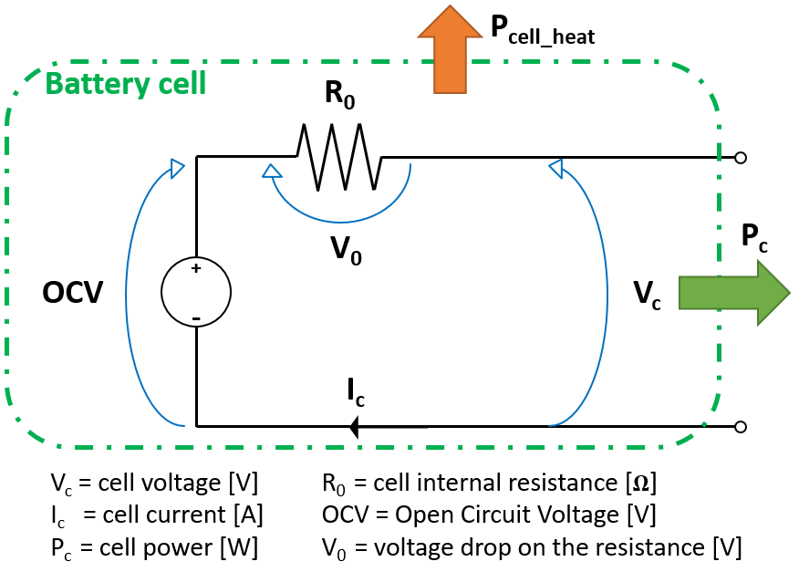
The efficiency of the drive battery is modeled using the equivalent-circuit cell model (see image below). The drive battery is seen as a set of battery cells with equal characteristics and size, with a certain combination of cells in series and circuits in parallel. Each cell of the battery suffers of a power loss that is proportional to the cell internal resistance R0 and the current flowing through it, that is transformed to heat. The performance obtained by the battery is then calculated by considering how many cells in series and parallel are constituting the battery.
Control strategy
The control unit of an HEV runs an optimisation strategy to control the hybrid powertrain and assign the target power to each component (engine and electric machines). The adopted strategy adopted in CO2MPAS is the Equivalent Consumption Minimisation Strategy (ECMS), which assigns an equivalent cost - in terms of fuel - to electrical energy use. The strategy evaluates the combination of engine and drive battery power that minimises the overall equivalent energy consumption.